 Electrical Impedance Mismatch
 Electrical Impedance Mismatch
Addressing the question of "What is an ImpedanceMismatch?" ... and its use in the ImpedanceMismatchMetaphor?:
When a "transmitter" emits a wave towards a "receiver", the "impedance" (a measure of the dynamic ohms-law relationship between the current and voltage of a source) of the two must match in order to maximize the power transferred from the transmitter to the receiver. If the impedance of the receiver does not match the impedance of the transmitter, a portion of the transmitter's energy will be reflected by the receiver and therefore unavailable to it.
As a metaphor, I understand the term to be a reference to the importance of a set of commonly held assumptions between a speaker and a listener, or a driver and drivee. In order to change the direction of a corporation, for example, the agent desiring to effect the change must be able to express the motivations for the change in language that is meaningful to the agents who can accomplish the change. If this condition is not met, the words of the change agent merely bounce off (are "reflected") and are therefore utterly ineffective. Hence the term "ImpedanceMismatch".
Contributors: TomStambaugh
On ElectricalImpedanceMismatch:
Let's see if I can remember this correctly... Impedance mismatch is when you have a difference in electrical impedance in the interface between an antenna and its base which causes problem with reflected waves. It also refers to the similar phenomena with other EM waves and acoustic waves.
It also applies to the coupling of any transmission media whether it be electrical, acoustic or optical. -- ChanningWalton
In other words, "It also refers to the similar phenomena with other EM waves and acoustic waves", though your wording is better.
Electrical / Signal:
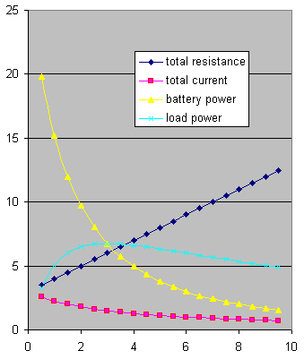
Say you had a battery and wanted to warm up a resistor with it really fast. Say also that you got to pick the resistor. What resistor would you choose? We can get a feel for impedance matching by working out this problem for a variety of resistors. Let's say it is 9 volt battery with 4 ohms of (lumped) internal resistance. We could try load resistors ranging from .5 ohms to 9.5 ohms, find the current through the total resistance, and then compute the power delivered to the load from this current. Use this spreadsheet: http://c2.com/wiki/impedance.xls.
Notice that small loads will allow a lot of current to flow and lots of power will be dissipated in the source, but not in the load, because there isn't enough resistance to absorb it. Power transfer increases as we try larger values until we reach a maximum with the 4 ohm resister (the source and load impedances match). With even larger loads, the reduced current fails to deliver as much power as before.
In a sense, this goes to the heart of the whole subject. When the impedance of two materials match, power transfer over the junction between the two materials is maximized. This applies regardless of whether the energy is electrical, optical, acoustical, thermal, or other. Optical impedance is index of refraction, btw.
The above considers static voltage; if the energy source is oscillatory -- a wave -- then at the junction where an impedance mismatch occurs, whatever energy is not transmitted across the boundary is in part dissipated as heat, and the rest is reflected back as a phase inverted replica of the original wave.
Above that reflection was described as a problem, but that is merely because the term "mismatch" is being used, which already implies that the goal is to maximize transmitted energy. The actual phenomenon of reflection thus caused can in fact be desirable, as in lasers and other uses of dichroic mirrors, certain kinds of antennae, resonance in musical instruments, etc.
A surprising amount of physics and engineering arises from/revolves around this. -- DougMerritt
In the generic case, an ImpedanceMismatch is indicated by the use of a transformer. If there is no ImpedanceMismatch, there is no need for a transformer and vice versa.
 EditText of this page
(last edited March 8, 2006)
or FindPage with title or text search